Protecting Your CPU Part 1: Digital Isolators
01 Aug 2019
What are digital isolators?
A digital isolator is a type of level shifter that utilizes magnetics to level shift communication buses between two devices that are on different power domains. These types of devices are pretty robust and can handle voltage differentials upwards of 1000V DC between the grounds of two devices. They can have uni or bidirectional channels that translate to the appropriate 1’s and 0’s that will meet the specifications of modern inter-processor communications, such as I2C at 400kHz and SPI at 10MHz. In this example I am using a Nucleus as the host and a GPIO expander as the device and will communicate between the two using I2C which requires bidirectional communication.
Why this actually matters
If you are not too familiar with electrical engineering you might be asking yourself what the point of this post is, and that is totally fair. The best example of why a digital isolator is actually useful is looking at a real world deployment of an electronic device. Say you build a device that needs to measure temperature and an end user is responsible for wiring that sensor up. In a perfect world the user would wire it to specification and everything would be just peachy. But in the off scenario where the user wires the temperature sensor up wrong and ends up applying voltages outside of your designated operating voltages, the chip used to measure said temperature would probably fail. Sometimes chips fail so hard that this user error can make its way back to the processor that is communicating with the chip and now the processor fails as well. But when utilizing an isolator, events that might cause a device to fail will not cause the host to fail. So even though temperatures cannot be read, the actual core of the device (the host) can still communicate and potentially give an alarm that it is unable to communicate with the temperature reading device. Utilizing isolators is just one small component in building robust devices that can handle a harsh real world environment.
Components and Datasheets
-
Digital Isolator: MAX14850
-
IoT Platform: Nucleus is an IoT gateway that communicates with the Tyrion Integration cloud and allows end users to view their data in real time through Tyrion’s web application. I used this device because I actually designed the hardware and software from the ground up for Tyrion. It was a platform I already had setup and had enough familiarity with to not have to google any pinouts or look up how to get I2C comms working. It runs an embedded linux operating system built using yocto and utilizes containers for its application programming. For the purpose of this tutorial, you can use really any embedded device that has I2C communication. The example code is written in C, but should be simplistic enough that you could modify it and throw it on a Raspberry Pi or Arduino with minimal googling.
-
GPIO Expander: MCP23017 is a gpio expander allows a host device with the appropriate communication interfaces a way to add more general purpose inputs and outputs. If you want to toggle a ton of LEDs and read a bunch of inputs you’ll likely need more I/O points and GPIO expanders are a simple way to gain access to more I/O. This type of I/O isn’t necessarily as fast as a pin connected directly to a processor because there will be a small delay from having to communicate and translate the communication into toggling or reading an input, but for most applications it will be speedy enough.
Hardware Setup
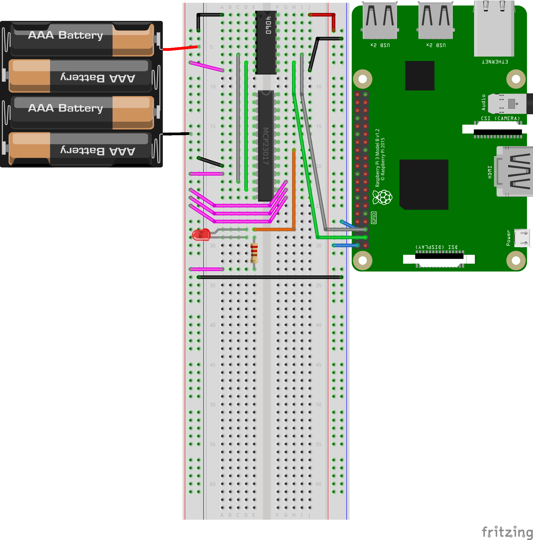
The hardware is actually pretty simple to setup for this project. I included a fritzing breadboard diagram using the Raspberry Pi. I wasn’t able to find a part in fritzing for the MAX14850 but found a component that has the same number of pins so the pin numbers and locations will be the same. The Raspberry Pi supplies 5V to the right red rail while the Pi’s ground or right blue rail is connected to the +5V on the voltage supply on the left side red rail. The Raspberry Pi’s ground is tied to the voltage supply’s +5V rail which creates a 5V differential between the Pi and the MCP23017; note that I did this to demonstrate the devices on either side of the digital isolator do not have to share the same reference voltage. So in short, the Pi is running off 0V to 5V while the GPIO expander is running off -5V to 0V and they are connected through the digital isolator. The wire colors and voltages/pins are denoted below.
- Red = 5V
- Black = 0V or Ground
- Pink = -5V
- Green = SDA the I2C data pin
- Grey = SCL the I2C clock pin
- Orange = GPIOA which is the digital output to toggle the LED
Also mad props to the guys at fritzing! I hadn’t used their software before this post but it is very simple to use and creates quite the visualization as opposed to taking pictures of a breadboard.
The code
I wrote this in C because I’m pretty fluent in it currently and had just written some I2C code that I could use as a reference, but the same result could be conceived using C++, python, nodejs, arduino, go, or any language that has an I2C communication library.
The code is commented pretty well so I’ll just dive into the functionality.
- Initialize the I2C device, address 0x20 if A0 A1 and A2 are connected to ground (r -5V in this scenario)
- Write to the config register and make port GPIOA pin 0 an output
- Write to the GPIOA register to toggle the output pin 0 to HIGH
- Sleep for 1 second
- Write to the GPIOA register to toggle the output pin 0 to LOW
- Sleep for 1 second
- Repeat for 3 cycles of a loop
1
2
3
4
5
6
7
8
9
10
11
12
13
14
15
16
17
18
19
20
21
22
23
24
25
26
27
28
29
30
31
32
33
34
35
36
37
38
39
40
41
42
43
44
45
46
47
48
49
50
51
52
53
54
55
56
57
58
59
60
61
62
63
64
65
66
67
68
69
70
71
72
73
74
75
76
77
78
79
80
81
82
83
84
85
86
87
88
		//////////////////////////////////////////////////////////////////////////////
		// Author: Curtis Reedy
		// Date: 8/1/2019
		// Description:
		// A simple program to toggle GPIO pins on a MCP23017 gpio expander IC
		// Compilation Command: gcc gpio.c -o gpio
		//////////////////////////////////////////////////////////////////////////////

		#include <stdio.h>
		#include <stdlib.h>
		#include <string.h>
		#include <errno.h>
		#include <unistd.h>
		#include <fcntl.h>
		#include <poll.h>
		#include <sys/types.h>
		#include <sys/stat.h>
		#include <inttypes.h>  // uint8_t, uint16_t, etc
		#include <linux/i2c-dev.h> // I2C bus definitions
		#include <linux/rtc.h>
		#include <sys/ioctl.h>
		#include <sys/time.h>
		#include <errno.h>


		int fd_gpio;
		// i2c address determined by 3 bit config of pins A0, A1, and A2
		int gpio_addr = 0x20;
		// buffer for holding registers and values
		uint8_t buf[3];
		// counter
		uint16_t i = 0;


		int main(void)
		{
			// open the i2c gpio expander
			if ((fd_gpio = open("/dev/i2c-1", O_RDWR)) < 0)
			{
				// if errors while opening, log it and exit
				printf("Error: Couldn't open device! %d\n", fd_gpio);
				exit (1);
			}
			// check that the gpio expander is available on the i2c bus
			if (ioctl(fd_gpio, I2C_SLAVE, gpio_addr) < 0)
			{
				// if errors while opening, log it and exit
				printf("Error: Couldn't find device on address!\n");
				exit (1);
			}

			// port config register 0x00 [IODIRA]
			buf[0] = 0b00000000;
			// 0xFE or 0b11111110 to configure GPIOA0 as an output and GPIOA1-7 as inputs
			buf[1] = 0b11111110;
			// write the buffer containing ADDRESS and VALUE to the gpio expander
			write(fd_gpio, buf, 2);

			// loop and toggle the led ON/OFF 3 times
			while (i < 3)
			{
				// register to write to 0x12 [GPIOA]
				buf[0] = 0b00010010;
				// value to write just GPIOA0 to HIGH
				buf[1] = 0b00000001;
				// write the buffer containing ADDRESS and VALUE to the gpio expander
				write(fd_gpio, buf, 2);
				// sleep for 1 second
				sleep(1);

				// register to write to 0x12 [GPIOA]
				buf[0] = 0b00010010;
				// value to write just GPIOA0 to LOW
				buf[1] = 0b00000000;
				// write the buffer containing ADDRESS and VALUE to the gpio expander
				write(fd_gpio, buf, 2);
				// sleep for 1 second
				sleep(1);

				// increment counter
				i++;
			}

			// clean up and close the i2c connection with the gpio expander
			close(fd_gpio);

			return 0;
		}
The level shifting
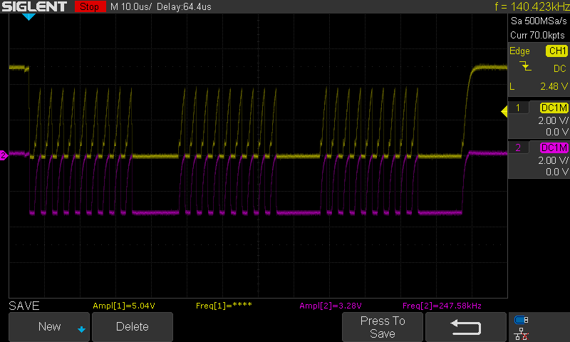
Now for the most important part, can the digital isolator actually level shift? Well yes, yes it can! So the first capture is of the I2C clock signal before (yellow) and after (pink) the digital isolator. The clock is running at 400kHz and as you can see they match up pretty well. There is a deviation in the signal but the VIL and VIH (these are thresholds where an input is considered high, VIH, and low, VIL) are precise enough for both devices to recognize the signal.
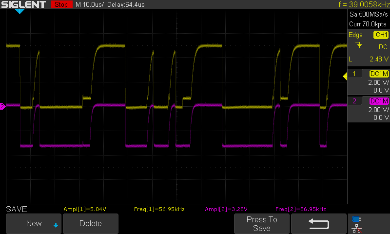
This second capture is of the I2C data signal and you can see that they also match up within specification because the host and device are communicating. Also full disclosure, I’m not sure what the small but short pulse is before the pin toggles on the host side is from and haven’t researched it, but communication is not affected because it is lower than the input low threshold voltage (VIL).
The third capture is one I2C transaction, specifically when writing to address 0x12 the value of 0x00; or writing a LOW to the output pin. You can see each bit in the communication and that it matches up to what the oscilloscope interpreted in its “decode” function.
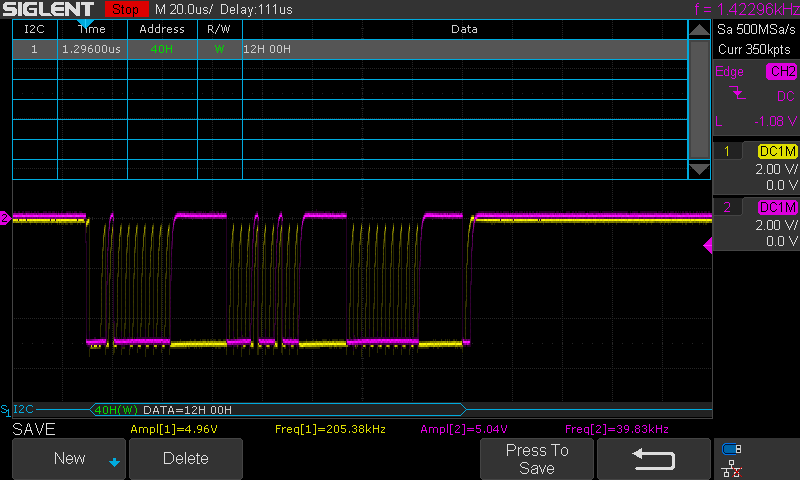
The last image is of the program above running without the 1 second sleeps. The config register is setting port GPIOA to 11111110 or all pins but 0 as inputs, and pin 0 as an output. Then the data in the decode shows a toggling of 1, 0, 1, 0, 1. So the digital isolator does work!

One last note on the oscilloscope captures, notice how on the left side the pink signal’s ground is directly in the middle of the screen vertically? Well the yellow signal is actually in the same location. So you can see that the GPIO chip is communicating with Nucleus when it’s reference voltage is 3.3V lower in the first two captures and 5V lower in the second two captures. Therefore the digital isolator actually accomplishes what it has advertised in its datasheet. Specifically for the MAX14850 this differential can be up to 850V DC while maintaining communication.
Closing Statement
Well there you have it, digital isolators are level shifters that don’t care about crazy voltage differentials, they will translate voltage levels while maintaining adequate speed for inter-processor communication; all while keeping your precious CPU safe from any malicious voltages.